

[Contributed by Graham Steel]
Related publications: [Ste06] and this WIRED article
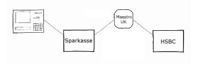
Suppose you bank in the UK, and you put your bank card into an ATM in Germany to withdraw some money. You type in your PIN, which has to be sent to the UK for your bank to authorise. The PIN is encrypted to prevent criminals from obtaining it. However, the ATM you use will not know the correct key for sending the PIN directly to your home bank. Instead, the encrypted PIN will pass through several nodes in the ATM network before it gets to the issuing bank. At each node, the PIN will be decrypted and re-encrypted under the appropriate key to be sent to the next node.
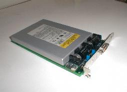
It is considered an unacceptable security risk for the PIN to appear in 'plaintext' form in the memory of a normal PC in a bank. So, all PIN decryption, re-encryption and verification is carried out inside tamper-proof hardware security modules (HSMs) like the one shown below. Note the tamper-proof, shielded enclosure, inside which all the processing occurs. Inside the enclosure is a CPU, a dedicated cryptoprocessor for standard encryption algorithms, and a small amount of memory. Should an intruder open the casing, or insert probes, to try to read the memory, it will auto-erase in a matter of nanoseconds.
The goal of these HSMs, with their strictly controlled APIs, is to prevent corrupt insiders in a bank from being able to obtain customers' PIN values. However, recent research has uncovered several ways in which this can be achieved [Clu03].
In order for a PIN to be encrypted by the standard encryption algorithms such as 3DES, it must be made into a 64-bit 'PIN block'. To complicate matters somewhat, different banks expect the PIN to be formatted into a PIN block in different ways. For example, for a 4-digit PIN, the VISA-3 format looks like this:
P1 P2 P3 P4 F F F F F F F F F F F F
Each character represents a 4-bit nybble. The Pis are the PIN digits, and the Fs are F hexadecimal. A problem with this format is that if two people have the same PINs, they will look the same when they are encrypted under the same key. To prevent this, the ISO proposed the ISO-0 format in ISO standard 9564:
B1 = 0 4 P1 P2 P3 P4 F F F F F F F F F F
B2 = 0 0 0 0 A1 A2 A3 A4 A5 A6 A7 A8 A9 A10 A11 A12
PIN Block = B1 XOR B2
The 0 at the beginning of B1 marks the block as being in format 0. The 4 indicates the length of the PIN, in this case 4 digits. The Ais in B2 are the 12 digits of the customer's personal account number (PAN). This way, two customers with the same PIN will not have the same encrypted block.
The API of the HSM may include a 'translate' command to allow blocks to reformatted ready to be sent to the next node. This introduces an attack. The problem is that in order to translate from ISO format to VISA-3 format, the user must re-supply the PAN so it can be XORed away to reveal B1. At this point, the HSM performs an error check, to see if all the PIN digits are of decimal value. Suppose that instead of supplying the correct PAN, the attacker supplies a modified PAN. This modification could be to XOR in the value 8 against the first digit, producing A1' = A1 XOR 8. If P3 is 0, 1, 8 or 9, the error check will still pass, since these values XOR 8 all give a decimal value. However, if the PIN digit is in the range 2-7, the HSM will signal an error, since these values all XOR against 8 to give a value between A and F hexadecimal.
By repeating this process with various values, an attacker can narrow down the value of the third PIN digit. He can only narrow it down to a pair of possible values though, since each pair of digits, 0 and 1, 2 and 3, etc., will give an identical pattern of errors and passes when XORed against values chosen by the attacker. However, by masquerading the ISO block as a VISA-3 block, the attacker can shift the PIN digits to the right, and extend the attack to determine the PIN digits uniquely.
There are several known families of PIN recovery attacks like the reformatting attack. Each customer for an HSM manufacturer will configure their HSMs differently, enabling different PIN block formats and different commands from the API. We have created a system, AnaBlock, which takes such a configuration and determines the most effective PIN block attack available to the intruder. It does this by using constraint logic programming in SICStus Prolog to build a large tree of all possible moves the intruder can make. Each node in the tree represents a state, where the attacker knows the PIN is in a certain range. For one particular attack, the edges in the tree will represent probabilistic choices, e.g. where the attacker tries a command, and the HSM may or may not report an error, depending on the actual (unknown) value of the PIN. The probabilities of each outcome depend only on properties of the state we are in, i.e. our attacks are represented by Markov chains (MCs). For a family of attacks, the tree will contain both probabilistic choices and non-deterministic choices, where the attacker chooses what he will try next. A family of attacks is thus represented by a Markov decision process (MDP). The idea is to analyse security in two stages: first, to generate using constraint logic programming an MDP representing all possible attacks, and then to use PRISM to analyse the MDP and choose the MC representing the most effective attack (we used a prototype version of PRISM which includes the facility to extract the MC satisfying the specified property). This is either the attack that determines the PIN in the lowest number of steps, or in situations where no such attack exists, the attack that reduces the PIN to the smallest number of possible values. Full details of the operation of AnaBlock will appear in a forthcoming paper [Ste06].
Below can be found an example fragment of a tree produced by AnaBlock and the code for the PRISM model which was used to generate it.
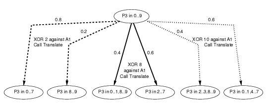
// Model for PIN Block attack analysis
// Auto generated by AnaBlock
// Author G. Steel, Aug 2005

// This file contains just a fragment of a full PIN cracking attack
// It is intended to illustrate the representation used for PIN ranges
// and corresponds to tree fragment shown in the final figure at
//   http://www.prismmodelchecker.org/casestudies/pincracking.php

mdp

module M1

P3_could_be0   : bool init true;
P3_could_be1   : bool init true;
P3_could_be2   : bool init true;
P3_could_be3   : bool init true;
P3_could_be4   : bool init true;
P3_could_be5   : bool init true;
P3_could_be6   : bool init true;
P3_could_be7   : bool init true;
P3_could_be8   : bool init true;
P3_could_be9   : bool init true;
P3_guessed      : bool init false;


PIN_Digit3       : [0..10] init 10;


Digit_Count       : [1..5] init 3;

// xor_in(2)

 [] !P3_guessed  & Digit_Count=3 & P3_could_be0&
P3_could_be1&
P3_could_be2&
P3_could_be3&
P3_could_be4&
P3_could_be5&
P3_could_be6&
P3_could_be7&
P3_could_be8&
P3_could_be9
 ->
// error case
 2/10: (Digit_Count'=4)&(P3_could_be0'=false) &
(P3_could_be1'=false) &
(P3_could_be2'=false) &
(P3_could_be3'=false) &
(P3_could_be4'=false) &
(P3_could_be5'=false) &
(P3_could_be6'=false) &
(P3_could_be7'=false)

 +
 8/10: (Digit_Count'=3)&(P3_could_be8'=false) &
(P3_could_be9'=false)
;

// xor_in(8)

 [] !P3_guessed & Digit_Count=3 & P3_could_be0&
P3_could_be1&
P3_could_be2&
P3_could_be3&
P3_could_be4&
P3_could_be5&
P3_could_be6&
P3_could_be7&
P3_could_be8&
P3_could_be9
 ->
// error case
 6/10: (Digit_Count'=3)&(P3_could_be0'=false) &
(P3_could_be1'=false)
 & (P3_could_be8'=false) &
(P3_could_be9'=false)

 +
 4/10: (Digit_Count'=3)&(P3_could_be2'=false) &
(P3_could_be3'=false) &
(P3_could_be4'=false) &
(P3_could_be5'=false) &
(P3_could_be6'=false) &
(P3_could_be7'=false)
;

// xor_in(10)

 [] !P3_guessed & Digit_Count=3 & P3_could_be0&
P3_could_be1&
P3_could_be2&
P3_could_be3&
P3_could_be4&
P3_could_be5&
P3_could_be6&
P3_could_be7&
P3_could_be8&
P3_could_be9
 ->
// error case
 6/10: (Digit_Count'=3)&(P3_could_be2'=false) &
(P3_could_be3'=false)
 & (P3_could_be8'=false) &
(P3_could_be9'=false)

 +
 4/10: (Digit_Count'=3)&(P3_could_be0'=false) &
(P3_could_be1'=false)
 & (P3_could_be4'=false) &
(P3_could_be5'=false) &
(P3_could_be6'=false) &
(P3_could_be7'=false)
;

 endmodule

 rewards

   [] true : 1;

endrewards
This work is part of the ongoing project 'Automated Analysis of Security Critical Systems', funded by EPSRC (grant number GR/S98139/01), with nCipher plc., a manufacturer of cryptographic hardware security modules, and CESG, the information assurance arm of GCHQ. For more details, see http://dream.dai.ed.ac.uk/projects/aascs.